Vulcan Beam Engine

I am starting to try and build a Vulcan Beam Engine from raw stock and not castings.

Full picture gallery: Vulcan Beam Engine Photo Gallery

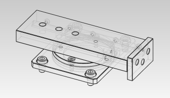
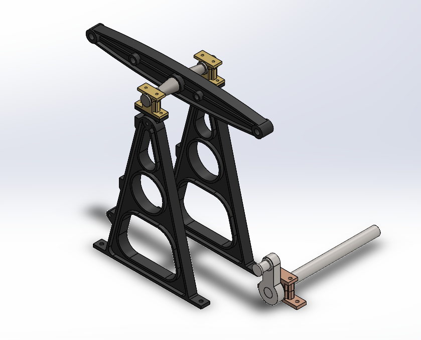
The first step was to convert the plans (purchased) into a CAD program to see how things fit together. So far I have just got the standards, beam created in CAD.

To try and see if not using casting is possible I am going to try and fabricate the beam from raw stock and silver solder bits together.

First stage in the CAD

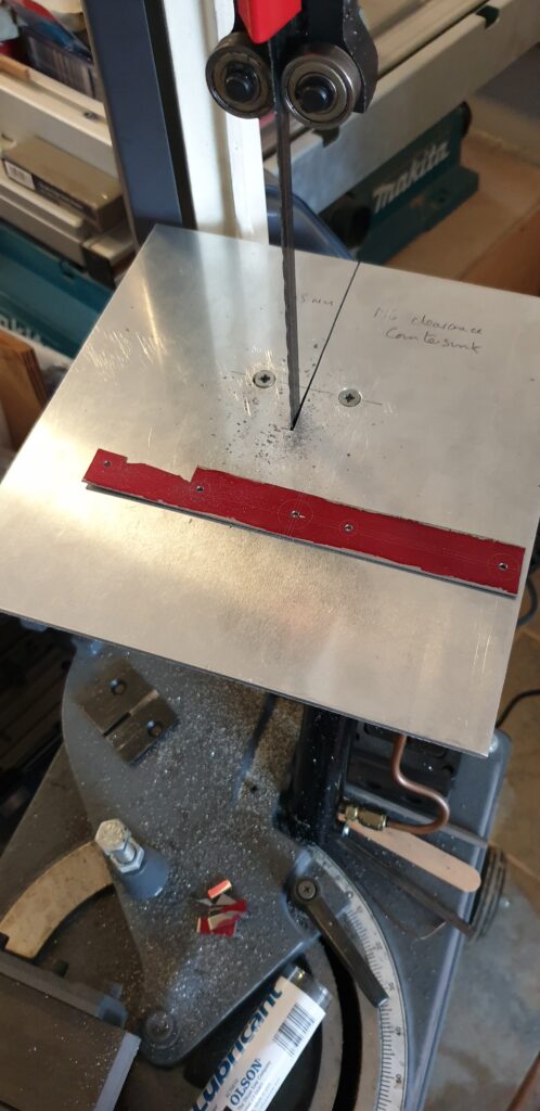
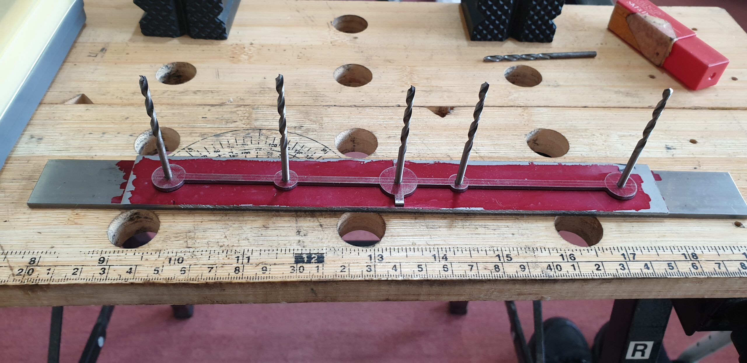
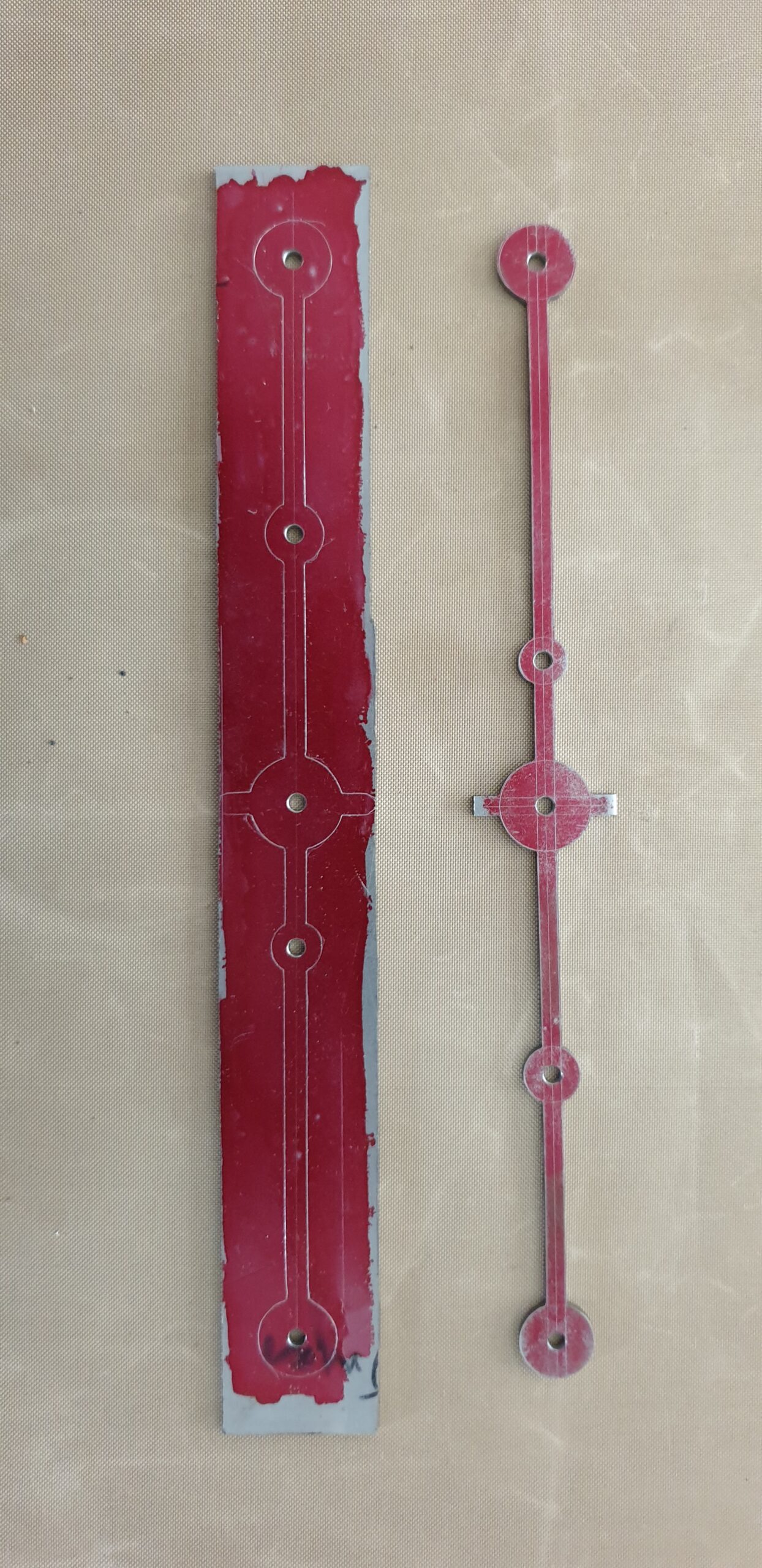
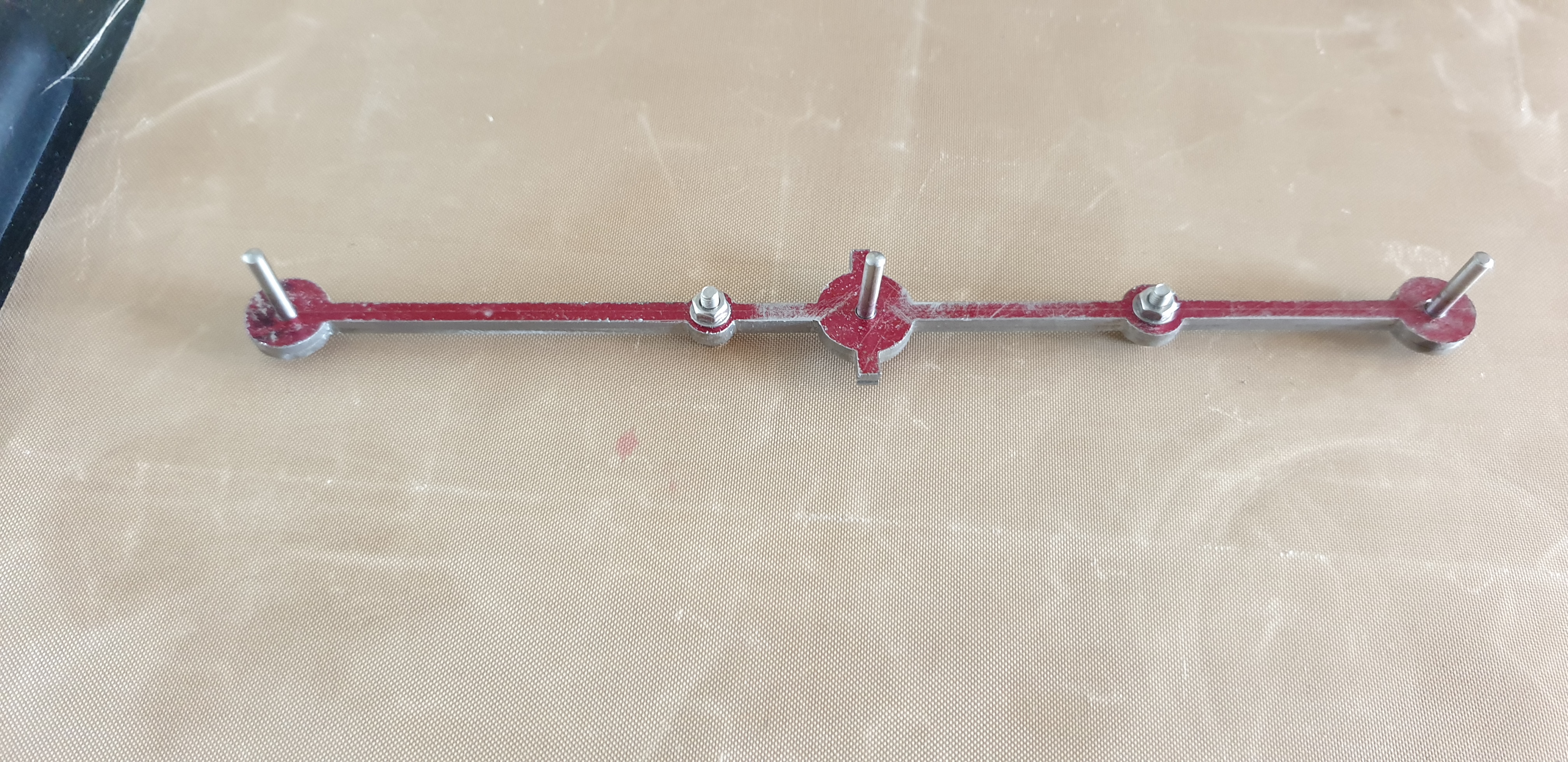
First step was to mark out for the holes and main features. Then to drill 3mm holes for registration.

Start of the Vulcan Beam Engine Beam

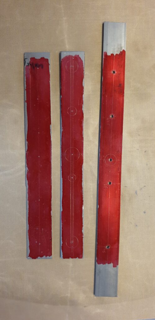
Then to use the bandsaw to rough cut the webs. First using an offcut of 4mm aluminium to make a rudimentary table for my horizontal bandsaw.

Modified Bandsaw Table and starting to cut some webs
Progress in cutting the web
Rough cut the first web

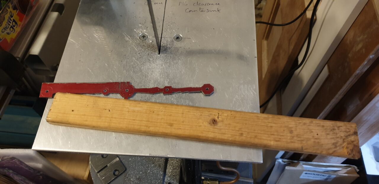
Now to use a 1″ belt sander to get to the line where possible. Then back to files.

Start of the filing with hand files
Transfer the markings to the second side using drills to provide the location
Markings transferred and ready to cut the second side on the bandsaw
Two halves joined with dowels and bolts for filing
Some 3D printed representations (top – full beam, middle – pattern for centre section, bottom – centre section marked and ready for cutting)
After silver soldering the webs and a bit of tidy up

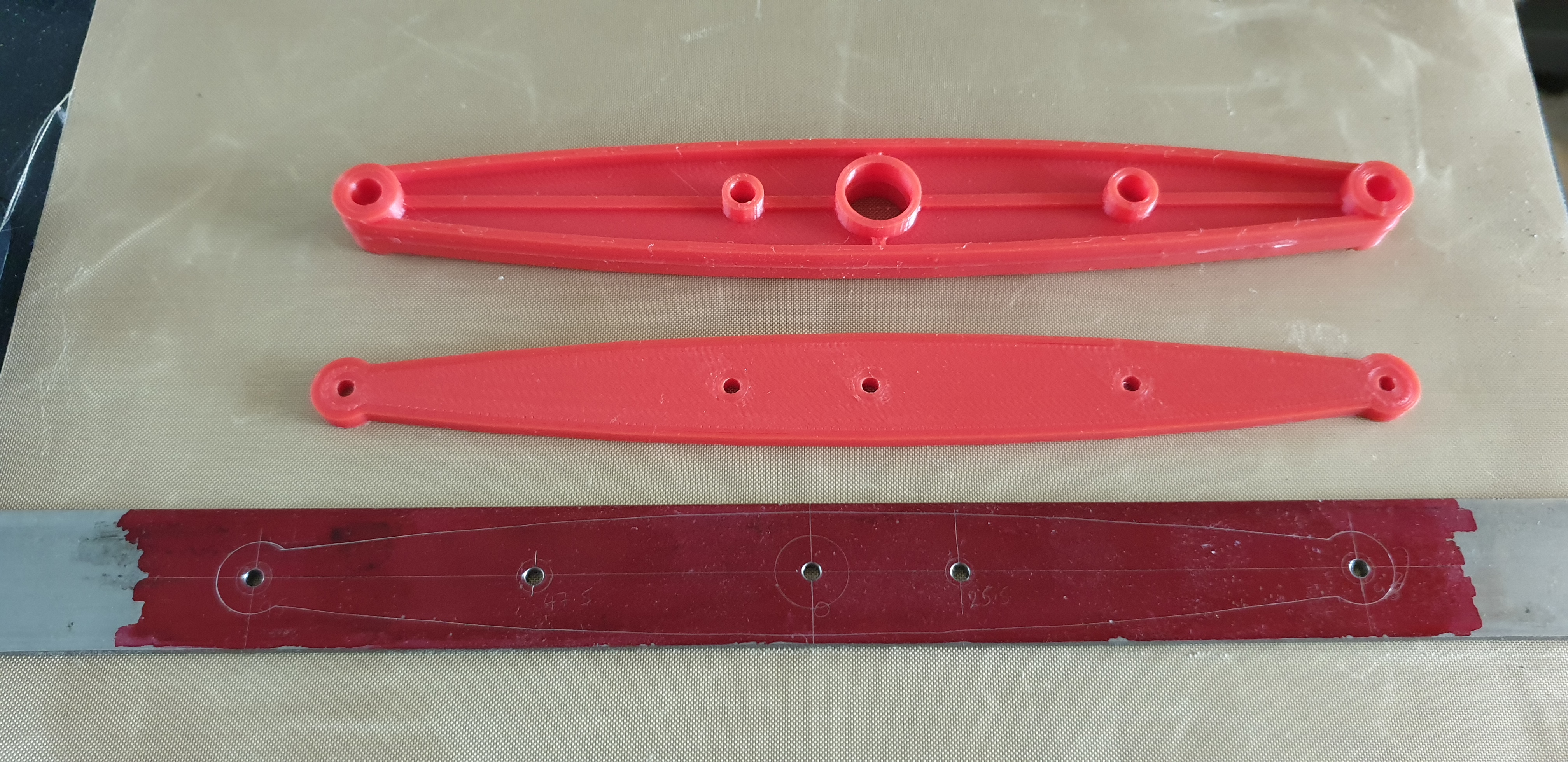
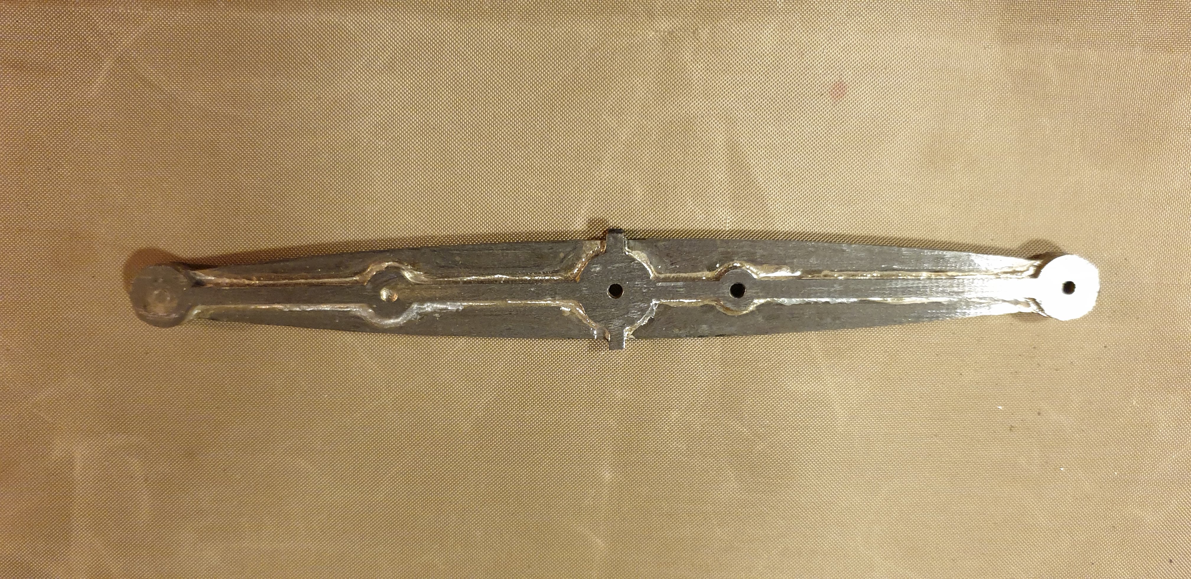
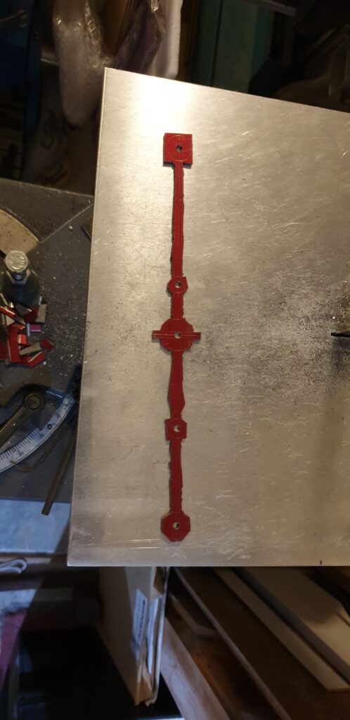
For the silver soldering I was trying to use an OxyTurbo Mapp/Oxygen torch with a small nozzle. However I think that this was too hot and actually was burning the flux before it could do its work. For the second side (the one shown above) I just used a normal propane torch which worked a lot better for this size of part. For the flux I first tried the easyflow flux, however I suspect that this was not good enough for the longer duration the soldering took. I then tried Tenacity 5A but didn’t like that due to the colour and not seeing if it was working. So for the second side I tried just tenacity 5 and this worked better for me.

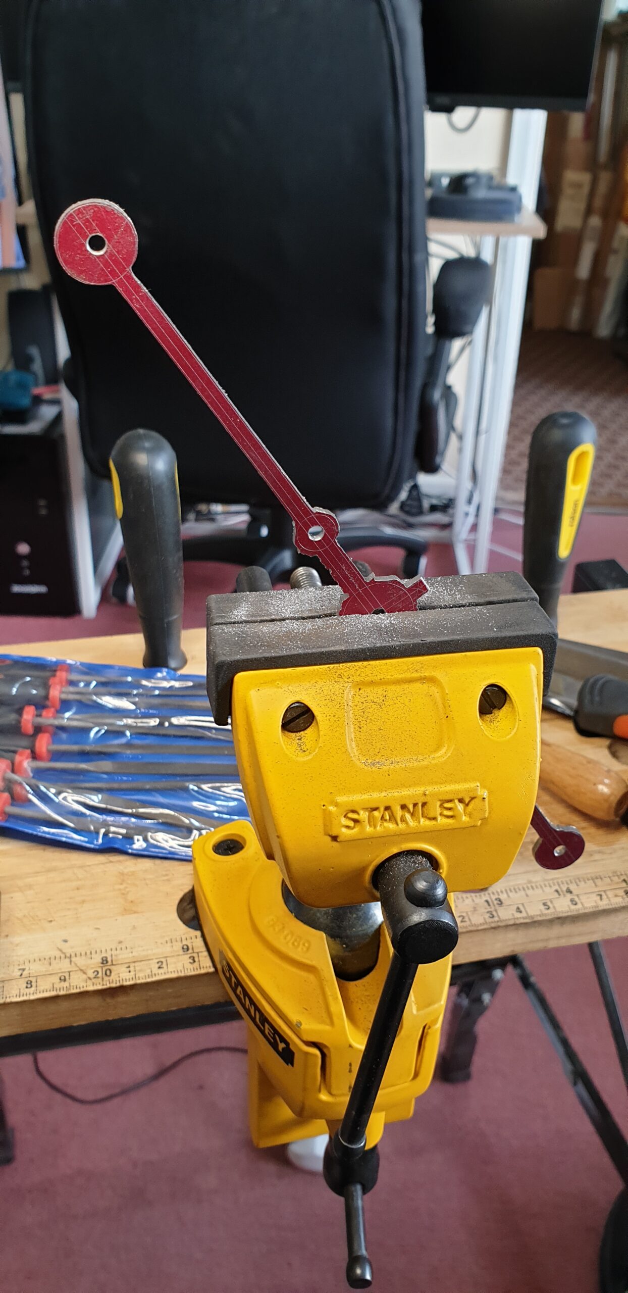
However, I need a lot more practice in silver soldering and trying different torches. So I have made the choice to buy the castings.

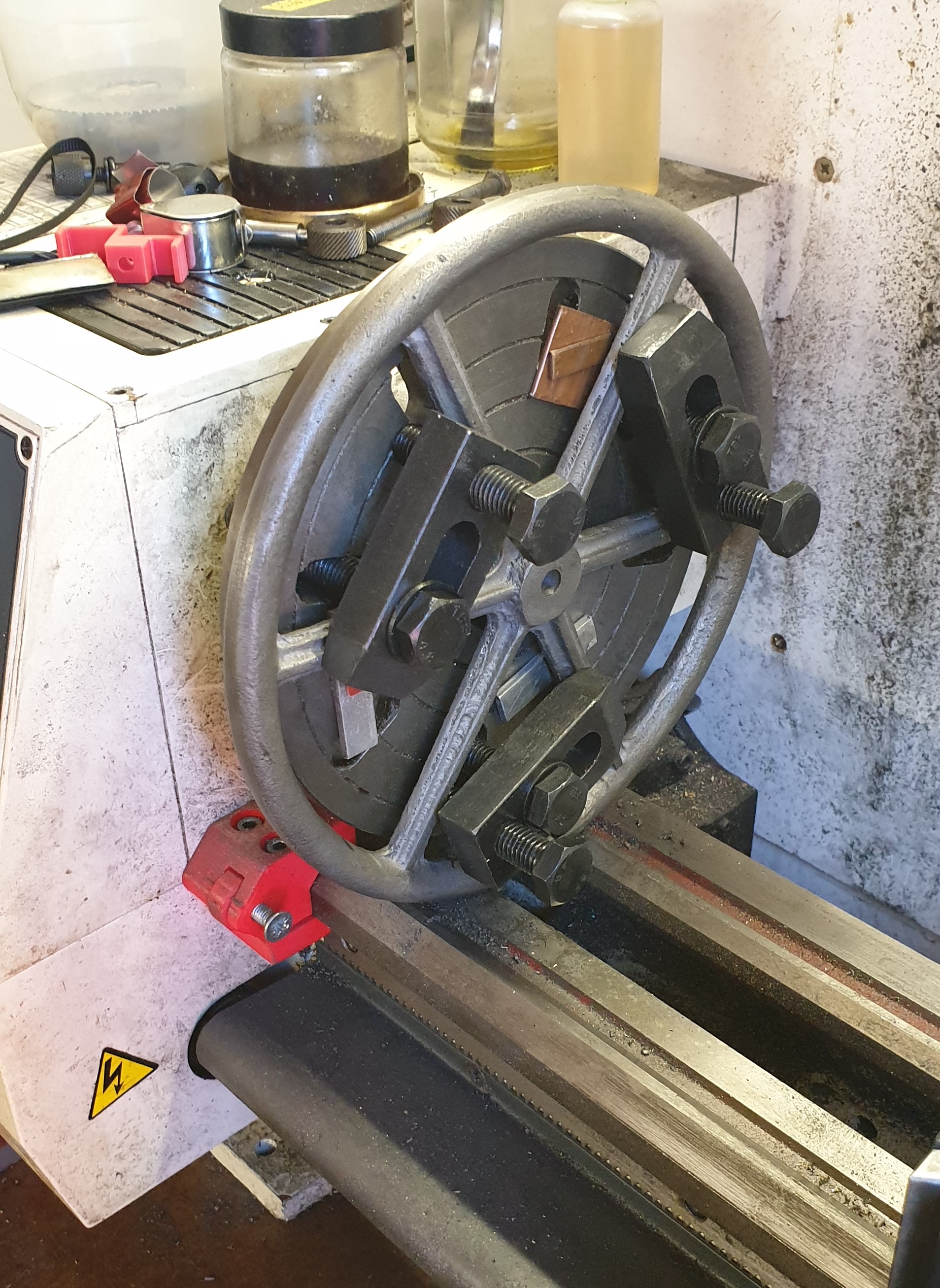
Starting with the casting for the flywheel. This was not a very good casting and may not work, but I will give it a go. It is also at the max limit of my lathe.

Some faceplate action for the flywheel at the limits of my lathe.

I also think that I need to make some more mounting straps etc.

Myfordboy Stove fan

This is my first real project.

Sorry, but I haven’t really been taking pictures of this. I may try and take a few of the parts.

So far I have found a minor air pocket in one of the castings and used HTS2000 aluminium brazing rods to fill the hole and then bored back to the final size.

Other machining issues have been because of lack of experience, but all have been solved.

Myfordboy Stove Fan

Myfordboy Stove Fan

CNMG1204 lathe tool holder

I recently bought some CNMG120404 inserts to try and was originally planning to make some holders. However I found some for a reasonable price on www.shop-apt.co.uk. 16mm shank CNMG insert holder

To make these work in my AXA tool post with the compound mod I just needed to remove 3mm from the base of the holder. This was quite easy to do in my mill (I used a 30mm carbide insert face mill).

Definitely pleased with the result. Now just to modify the left hand tool I also purchased and then make a tool to use the obtuse cutting edges (the ones I have seen on the net have too large a shank size and are too costly for me).

SC4 New Compound

This has been a great success. Also having the three holes for the toolpost is good for rigidity when using a parting tool (you can move the tool within the footprint of the compound to avoid tilting).

However there is a fair old amount of backlash due to using the original leadscrew/mount. Either a shim is required or even better would be a change to using dual bearings in a similar way that I did on the C2A mod.

Sieg SC4 Lathe

I have decided to upgrade my lathe from the C2A to the SC4.

It is a much sturdier machine in all aspects and I look forward to actually using it. But it will take a bit of work to actually get it into a position to use… And then there will be the mods to be able to use my AXA toolpost…


Sieg C2A Lathe from Axminster

So far I have performed some of the basic tweaks (gibs etc). However I have had my rotational DROs fail on both the cross slide and compound. Perhaps they didn’t like the extremes of environment in my shed. I suppose that I am going to have to make some more items to replace these with a normal handle and bearing support and then add some cheap digital scales.

I have already created a “mounting block” to replace the compound to aid general stability for ordinary operation.

The taper roller bearing mod has now been performed and I feel that it has increased the stiffness of the head. However I appear to have a slightly out-of-true Headstock MT3 taper.

The present addition is an AXA-100 size toolpost. It hasn’t been used yet because I have to make a new support block and a new compound due to the extra size of the toolpost.

A new compound slide has been made and the new tool post works great.